Deterministic ground truth from video.
Tattva3D converts monocular video and known scene constraints into auditable camera poses, trajectories, and speed estimates for forensic analysis and liability determination.
Working components of the current analysis pipeline.#
Lens Validation
Intrinsics and distortion are solved from measured 2D ↔ 3D correspondences and checked by reprojection residuals on held-out points before any downstream estimate is used.
Camera Trajectory Recovery
Per-frame pose is recovered from tracked image points and known scene geometry. Each frame's solution is independent and inspectable on its own merits.
Constrained Motion Analysis
Velocities and trajectories are derived in scene-aligned units from constrained motion, with explicit uncertainty — never a single unqualified number.
Reviewable Runs
Inputs, parameters, and intermediates are logged so a run can be reproduced and challenged step by step from the audit manifest.
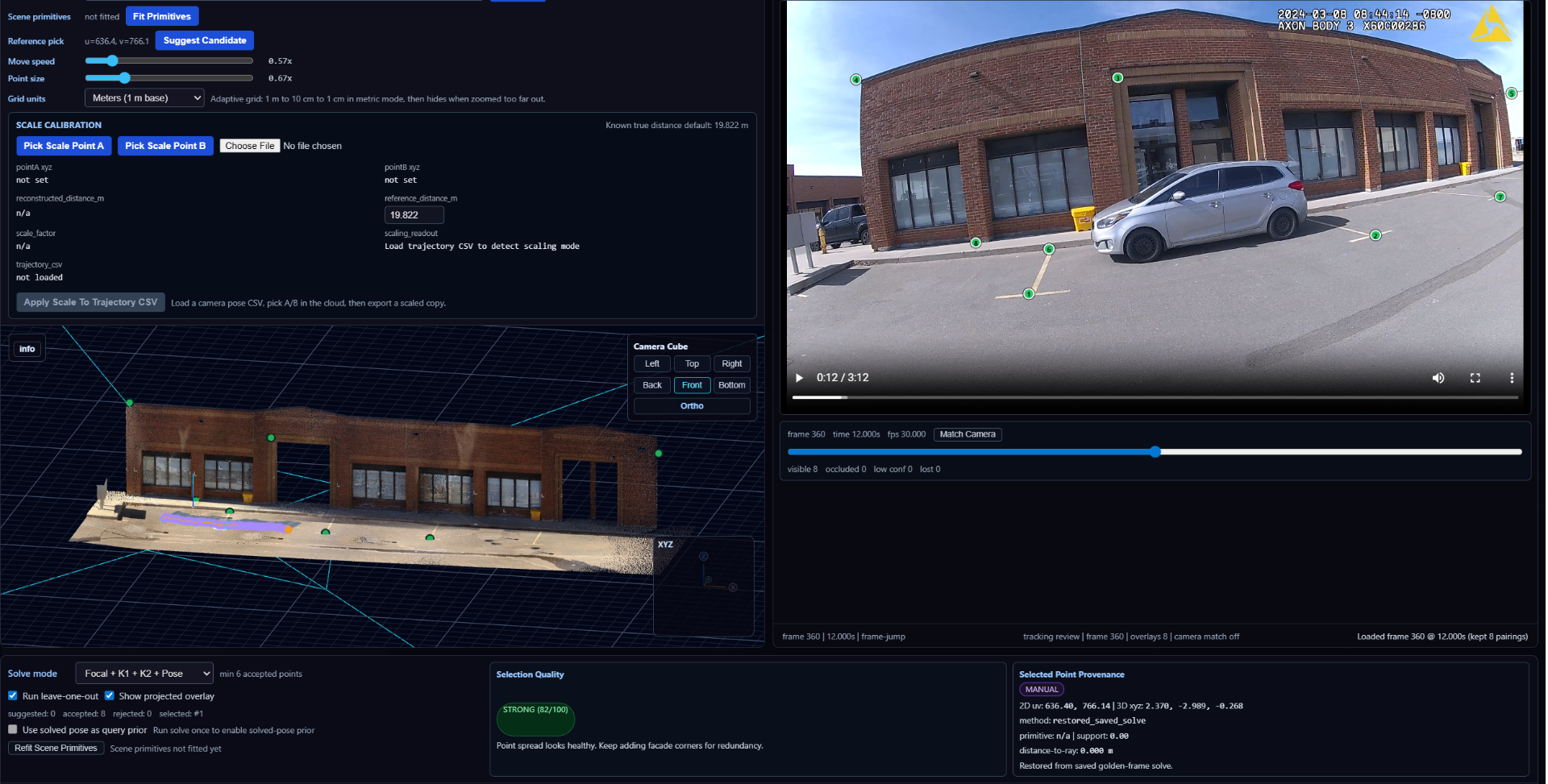
Camera-to-scene alignment from measured correspondences.#
The foundation underneath every downstream estimate: a calibrated lens and a set of measured 2D ↔ 3D correspondences are used to lock the camera into scene-aligned coordinates. Reprojection residuals on held-out points keep the alignment honest.
Everything that follows — per-frame pose, constrained motion, speed — is derived from this anchored frame of reference rather than from inferred geometry.
Scene-constrained human motion from monocular video.#
An early prototype recovering an individual's motion from a single video and re-expressing it inside the same constrained scene geometry used for camera and vehicle estimates. The human figure is anchored to measured ground and the recovered camera — not free-floating.
Note the vehicles in the background: they jitter frame-to-frame because, in this clip, they are tracked without a metric anchor of their own. That instability is the exact failure mode the next prototype addresses — by constraining each vehicle to scene geometry and known dimensions, rather than letting it drift.
Exploratory R&D, not a shipped capability. Shown to illustrate the direction: extending the same scene-constrained, inspectable approach from vehicles to people.
Footprint recovery for subject path reconstruction.#
Building on the recovered human motion, per-step footfall contacts are extracted and projected onto the scene-aligned ground plane. The result is an explicit subject path — a sequence of measured ground contacts in scene coordinates — rather than a free trajectory floating in space.
Because the path is derived from constrained motion against known geometry, it reconstructs on surfaces that leave no physical trace: asphalt, tile, concrete, indoor flooring. The footprints exist in the analysis even when they never existed at the scene.
Exploratory R&D — shown to illustrate how scene-constrained motion extends into defensible path evidence for pedestrian and bystander analysis.
Semantic vehicle masking for constrained speed estimation.#
The direct response to the background jitter seen in the previous clip. Here, the vehicle is segmented per frame and locked into the same scene-aligned 3D environment, with the vehicle's known physical dimensions acting as a metric anchor. The bounding box stays dimensionally consistent across frames instead of drifting.
That dimensional anchoring is what turns per-frame masks into a defensible speed reading: motion is derived from constrained, measurable inputs rather than an unconstrained track.
Exploratory R&D — not a validated speed measurement. Shown to make the working approach visible.
Dimensionally anchored vehicular meshes.#
The background jitter seen in earlier clips — vehicles drifting frame-to-frame because they lacked a stable metric anchor — is reduced here by constraining the vehicle representation with known real-world dimensions and placing it into scene-aligned coordinates.
Rather than tracking an unconstrained 2D bounding box, the system uses the vehicle's known physical dimensions as a deterministic constraint on scale and pose. The visible mesh is a demonstrative proxy driven by those constraints, not the source of measurement itself.
This is the pieces coming together. Scene calibration, constrained segmentation, vehicle dimension anchoring, and camera-relative pose estimation combine into a single inspectable output: a vehicle track derived from geometry and measurements the solver is not allowed to freely invent.
Exploratory R&D — shown to illustrate the emerging pipeline from evidence to measurement. Final forensic use requires validation against sanitized real-world dashcam datasets, analyst review, residual reporting, and auditable outputs.
Source-agnostic. Trust-aware.#
Tattva3D is being built to ingest multiple spatial reference layers without treating them as equal sources of truth. A survey point cloud, an AI-generated mesh, a Gaussian splat, and a third-party map layer can all be useful, but they should not carry the same evidentiary weight.
The goal is not to blindly trust every incoming 3D source. The goal is to preserve provenance, classify each layer by evidentiary role, and keep measurement, assistance, and demonstration separated inside the workflow.
As reality-mapping datasets mature, including point clouds, meshes, orthomosaics, city-scale map tiles, Gaussian splats, and robot/drone spatial layers, Tattva3D is positioned to ingest them into a forensic workflow while keeping the deterministic record protected.
Source-agnostic does not mean trust-agnostic. Every imported layer must declare what it is allowed to do: drive measurement, assist analyst review, or provide demonstrative context only.
Measured spatial data that can support validation.
Survey point clouds, DXF files, LiDAR scans, total station data, orthoimagery with ground control, calibrated camera intrinsics, known vehicle dimensions, and manually verified landmarks can form the deterministic reference layer used for measurement, camera solving, residual reporting, and audit output.
Useful for proposals, initialization, and analyst acceleration.
SfM, VGGT-style reconstruction, SLAM trajectories, segmentation masks, semantic proposals, and AI-generated geometry can help initialize a solve or provide visual context. They are not accepted as measurement by default. They must be reviewed, constrained, and validated before influencing the forensic record.
Powerful scene context without contaminating measurement.
Third-party map layers, city-scale reality meshes, photorealistic tiles, Gaussian splats, orthoimagery backdrops, and generated scene visuals can help explain the reconstruction. These layers can make reports and courtroom demonstratives easier to understand, but they remain downstream of the locked forensic data package.
Tattva3D binds video evidence to the best available spatial reference layer, but the software must always preserve what each layer is allowed to be: measurement, assistance, or illustration.
{
  "sourceType": "survey_point_cloud | sfm | vggt | gaussian_splat | map_tile | ai_mesh",
  "evidentiaryRole": "forensic_reference | assistive | demonstrative",
  "scaleKnown": true,
  "groundControlAvailable": true,
  "analystReviewed": false,
  "mayDriveMeasurement": false,
  "mayDriveVisualization": true
}Many video-to-3D systems infer geometry the camera never observed. In a forensic context, an inferred surface is not evidence — it is an assumption presented as a measurement.
Tattva3D works the other way. Every estimate is anchored to a calibrated lens, tracked image points, and scene geometry that can be measured or surveyed. Nothing downstream is computed from unseen structure, and every intermediate remains open to inspection.
The output is not a guessed scene. It is an inspectable chain from evidence to measurement.
Forensic engineers
Recover scene-aligned measurements from video evidence with a defensible computational chain.
Accident reconstruction teams
Pair video with survey or scan data to constrain trajectories and speeds without proprietary scene reconstruction.
Insurers and liability teams
Inspect, reproduce, and challenge measurements without relying on a black-box estimate.
- —Not a generative video-to-3D toy
- —Not a photogrammetry replacement
- —Not a black-box “AI says the speed was X” system
- —Not optimized for visuals before mathematical validity
Work today centers on constrained motion recovery from monocular video. Each component below is held to the same requirement: the result must be reproducible from a logged manifest by an outside reviewer.
- F.01Lens calibration
- F.02Tracked points
- F.03Per-frame camera pose recovery
- F.04Constrained motion analysis
- F.05Speed estimation
- F.06Auditability and rerunability